The Calibrating Coil System
(CCS) of LEMI design has four square coil rigidly mounted on massive table
and Clarke-Hess instrument set for precision calibration of magnetic field
sensors in wide frequency range, see Figs. 1, 2. The calibrating process can
be provided both in hand and fully automated mode, with use of specially
developed LEMI software and usual desktop or laptop PC. For convenience of
tested sensors placement the table surface is displaced below the coils axis
at distance 43 mm.
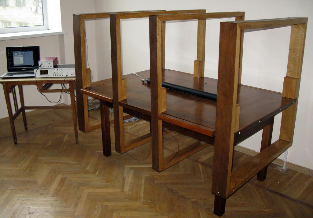
Fig. 1. Calibrating Coil
System
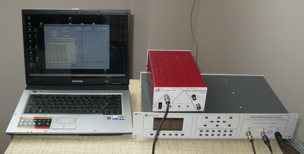
Fig. 2. Clarke-Hess
measuring instrument with amplifier LPA01 and control notebook
The coils’ configuration is
shown in Fig. 3. This configuration was calculated and optimized by computer
simulation for provision of maximal compactness at given maximum magnetic
field nonuniformity (in given cylindrical volume) and upper limit of
frequency range.
The calculated coils’
parameters are shown in Table 1. The maximal calibrating coils’
nonuniformity on cylindrical surface of radius R=0.05 m and 0.1 m against
distance from coil system centre along coils axis is shown in Fig. 4. From
this plot it is clearly seen that CCS provides magnetic field sensor
calibration in cylindrical volume of diameter 0.2 m and length 1.2 m with
nonuniformity less than 0.01 (1%). For sensor with length less than 30 cm,
this nonuniformity is less than 0.1%.
The measured CCS constant
K, after coil assembling, is 15.6 nT/mA ± 0.1%.
The magnetic field B
in the CCS centre equals
B = I*K,
where I is current in
coils.
Note 1.
For provision of maximal accuracy (about 0.1%) at current measurements in
wide frequency range it is recommended to use reference resistor R
with total error less than 0.03%. Thus the current in coils equals
I = U/R,
where U is voltage on
reference resistor. For provision of maximal precision the voltage U
should be measured with error less than 0.1%. At greater allowable errors it
is possible to use for U voltage measurement the data from CHI input
1 (see p. 11-3 of CHI “Instruction Manual”).
Typical electric circuit at
magnetic sensor calibrating procedure is shown in Fig. 5.
In upper part of CCs
frequency range the correction factor K1 for measured
current I is applied
I = K1*U/R,
where
K1 = ((1-(f/f0)2)2+(4*10-9*f)2)-0.5,
f
is current frequency, f0 = 2.8*105 Hz is coils
resonance frequency. For example, at frequency f = 10 kHz K1
= 1.0006, however at f = 200 kHz K1 = 1.4289.
Note 2.
At DC measurements a “+” clamp of DC power supply should be connected to red
clamp of calibrating coils. A “-” clamp of DC power supply should be
connected to black clamp of calibrating coils via reference resistor R.
In this case magnetic field vector B will be oriented along coil axis
from table side with input clamps to opposite table side.
Fig. 3. The coils’
configuration
Note 3.
In AC mode maximal current in coils is limited by the maximal current of
LPA01 (0.75 A, peak value, see LPA01 brochure). In DC mode the maximal
current is limited by dissipated heat in winding and time. As a current
source in DC mode any stable and low noisy power supply can be used. The DC
value in calibrating coils I and time
of continuous work in DC operation mode T can be described by simple
equation
T = T0*(I0/I)2,
where T0 =
1 hour, I0 = 1 A, I ≤ 4 A.
Table 1. Calculated
coils’ parameters
|
Coil
parameter |
Value |
|
Inner
coils’ side length, m |
1.09 |
|
Outer
coils’ side length, m |
1.05 |
|
Distance between inner coils, m |
0.42 |
|
Distance between outer coils, m |
1.48 |
|
Number
of turns in inner coils |
6 |
|
Number
of turns in outer coils |
10 |
|
Wire
diameter, mm |
1.1 |
|
Coils
total DC resistance, Ohm |
2 |
|
Winding
pitch (at one turn), mm |
20 |
|
Coils
constant (calculated), nT/mA |
15.581 |
|
Coils
constant (measured), nT/mA |
15.6±0.1% |
|
Coils
resonance frequency, kHz |
280 |
|
Coils
frequency range, kHz |
0 - 200 |
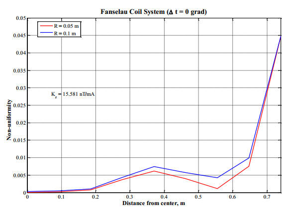
Fig. 4. Maximal magnetic
field nonuniformity on cylindrical surface of radius R=0.05 m and 0.1 m
against distance from coil system centre along coils axis
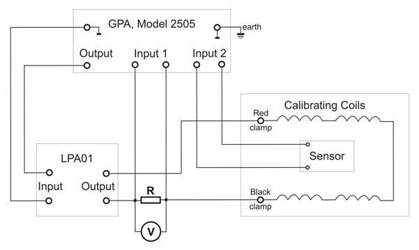
Fig. 5. Typical electric
circuit at magnetic sensor calibrating procedure